| Antennas |
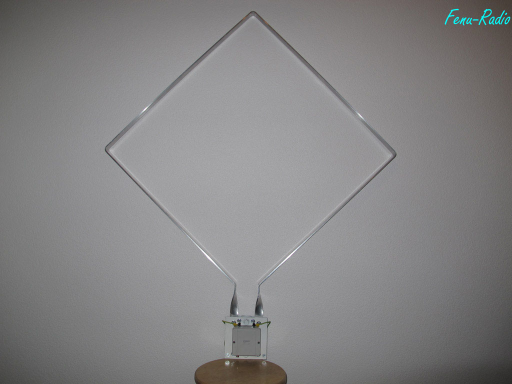
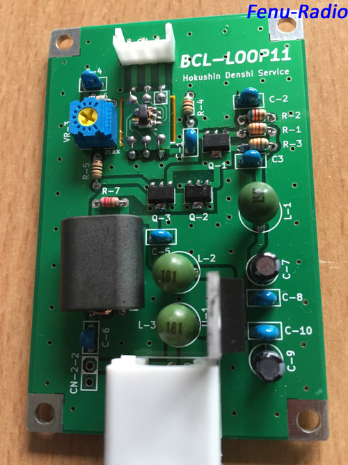
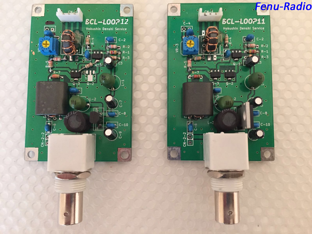
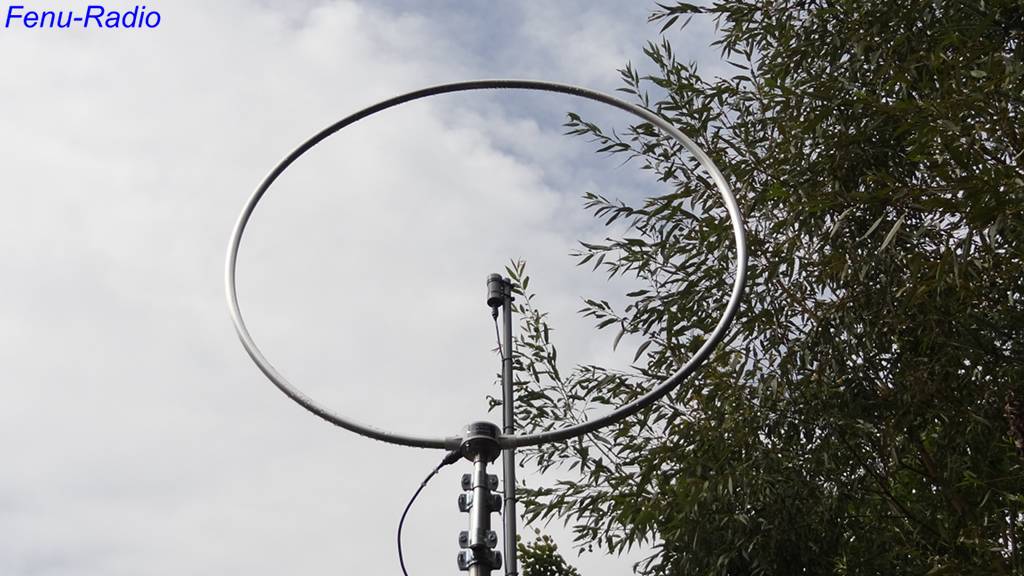
BCL-Loop12 beta During my daily internet searches for hobby-relevant news, I came across a blog by a Japanese SWL where there was a report about the BCL-Loop11. According to the Japanese SWL , this loop amplifier- called BCL-Loop11- produced good reception results. Since this blog was in Japanese, the Google-translation resulted in a very strange-sounding text. It took a while before I was able to find out the manufacturer of the loop and his web page, which was also in Japanese. I sent the developer Susumu Hashimoto a mail asking him to send me a test unit of this amplifier. The answer from Japan did not take very long. Susumu was surprised at this request and sent me a test unit of the BCL-Loop 11. After a few days I received a Jiffy bag from Japan.
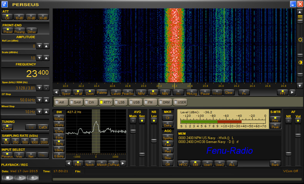
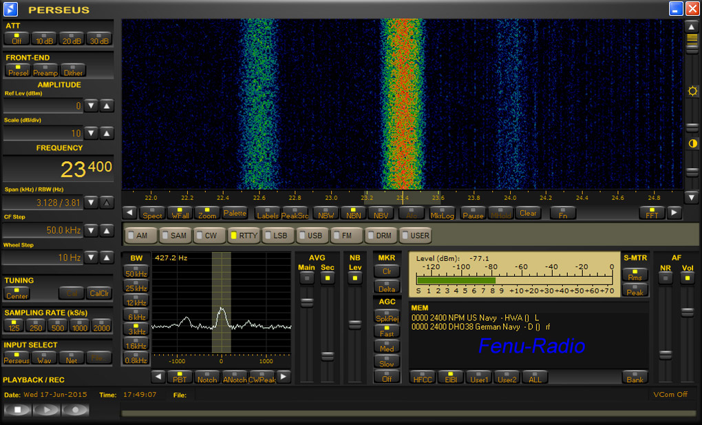
Now I could start. As always, I started with the lower frequencies. I tried to receive the German military station DH 038 on 23.4 kHz. Unfortunately, I did not succeed. Almost all stations below 500 kHz could not be received at all or very weakly at best. Further tests showed that that the Loop11 was just not designed for the lower frequency ranges. Only medium wave stations could be heard well. Shortwave stations, on the other hand, could be received very well and were on par with the NTi ML200. Starting at about 18 MHz there was slight loss of sensitivity, which was not too tragic, however. A fast series of tests with other loop amplifiers showed where the Loop11 has its shortcomings. These start at the lower frequencies of the long wave spectrum up to approx. 1000 kHz. The small Loop11 has potential, after all and on shortwave it was in the same league as the other well-known loop amplifiers. On shortwave, the SNR (signal/noise ratio) was identical. Günter (DL4ZAO), a hobby friend and antenna expert, who was following the discussion in the dx-unlimited forum, made some suggestions to improve the Loop11, which I sent to Susumu Hashimoto. I reported the problems and the importance of the lower frequency ranges for us Europeans. Of course, I told him that the Loop11 worked very well on shortwave. In order to push the envelope, I connected the Loop 11 amplifier to my big loop with its 4 square meter area. The amplifier proved to be very patient; there were no big signal problems. . With this big reception area, stations on long wave and even below could be received. On and off, the time signal on 60 kHz was heard very well.
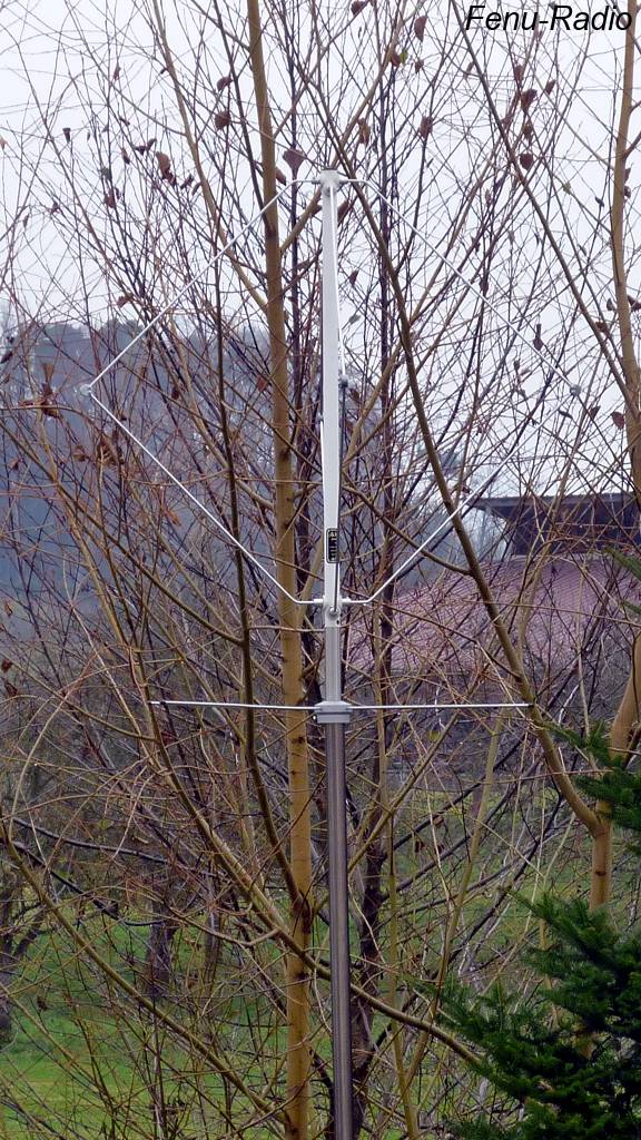
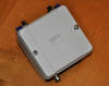
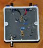
After some days, Susumu Hashimoto replied and thanked me for the valuable suggestions which he put into practice immediately. After some weeks, I received again mail from Japan with three amplifier boards: two Loop11 MK2 and a Loop12 beta. In the case of the Loop11 MK2 the input transformer had been changed. The Loop12 beta's circuits had been optimized and better components were used. The final version of the amplifier board of the Loop12 is in production and will be available soon.
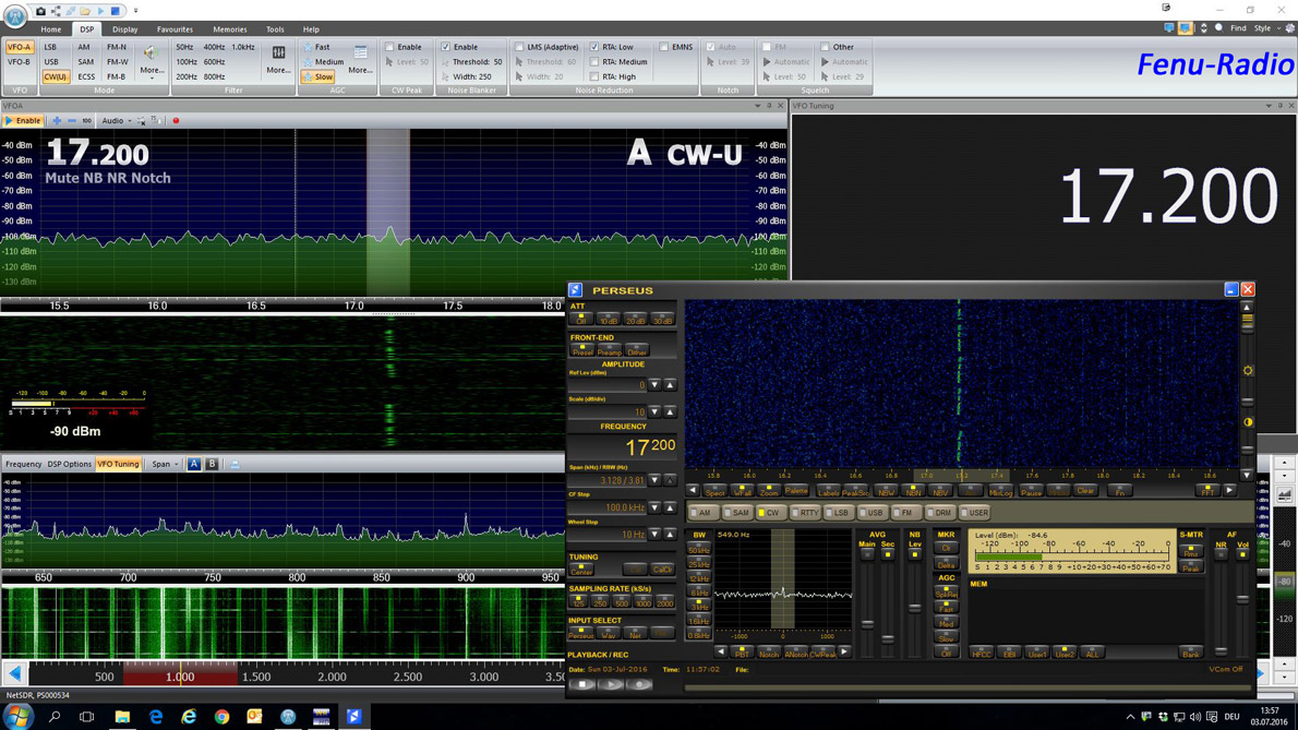
How does the Loop 12 beta play? This was the right start: When the station SAQ in Sweden sent Morse code on 17.2 kHz, the Loop12 beta was ready for testing. And lo and behold: the big loop received SAQ very well. The changes in the circuits and the new components showed good results.
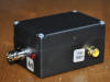
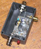
Reception of VLF and low wave signals was convincing and on par with the NTi ML200. This antenna received weak signal slightly more quietly, but the level was the same. On medium wave the differences between the Loop12 beta and the ML200 were even smaller with the ML 200 being a little quieter. On short wave, reception was convincing and there was no reason for criticism. The 10/11m band was received equally well with both amplifiers. Conclusion The Loop12 made a very good impression. The circuits of the amplifier are not very sophisticated but do well and do not have to hide from the bigger ones. Strong signal performance is also very good. At no time did I notice any intermodulation or FM-interferences. The Loop12 can be purchased directly from the manufacturer including a bias tee and a waterproof enclosure. Website from Manufacturer: http://blog.goo.ne.jp/shin749r Mail-address: sj30sin_749r@ybb.ne.jp posted 12.08.2016
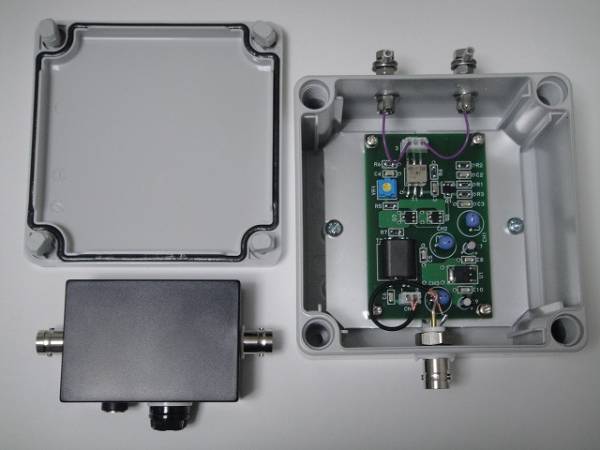
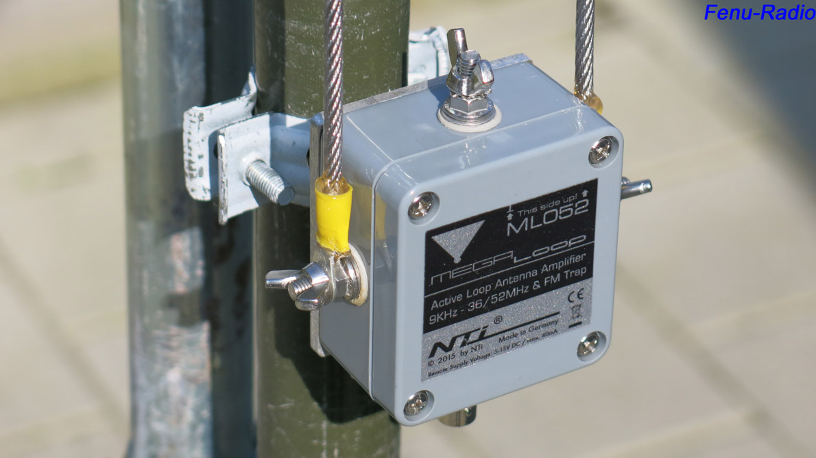
The story of the NTi ML052 starts at a DX-Camp which took place near a FM-radio station. The Dxers wanted to compare the ML200 with other H-field antennas. They soon found out that the ML200 did not work as expected; there were overloads and strong interferences from a FM-station which was not even 200m away. Both the other H-field antennas, the HDLA and the Bulgarian AAA1C showed no such effects. Unfortunately, it was not taken into account that the ML200 is a broadband antenna for frequencies up to 170MHz. The HDLA and the AAA1C on the other hand, are designed for frequencies up to 55 MHz and have also blocking filters. No wonder then, that the ML200 did not meet the expectations of the DXers. Because of this experience, Mr. Rudolf Ille started to develop an alternative antenna which would also work in the neighborhood of FM-stations. After some time, he sent me the ML052 for comparison with the ML200.
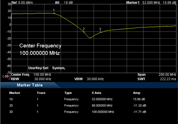
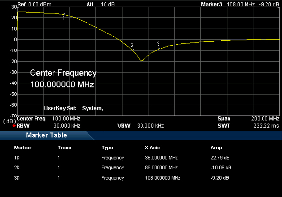
Function of the FM-blocking filter The FM-blocking filter is not a conventional low-pass filter which simply attenuates all frequencies above a certain point. The FM-blocking filter used here is a notch filter. It is designed in such a way that it attenuates up to 32dB (High-Gain) at the beginning and the end of the FM spectrum. Such a filter is not only made use of for the ML052 but also for the well-known HDLA-Loop Amplifier.
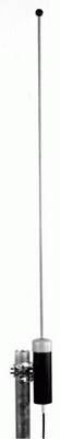
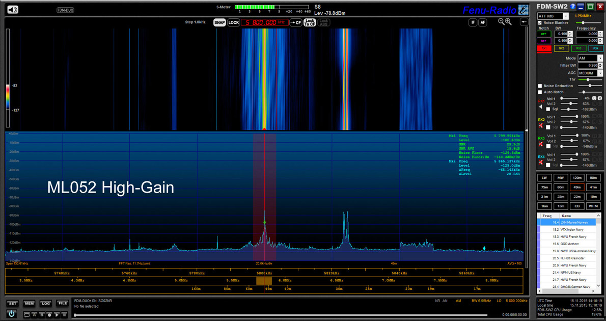
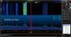
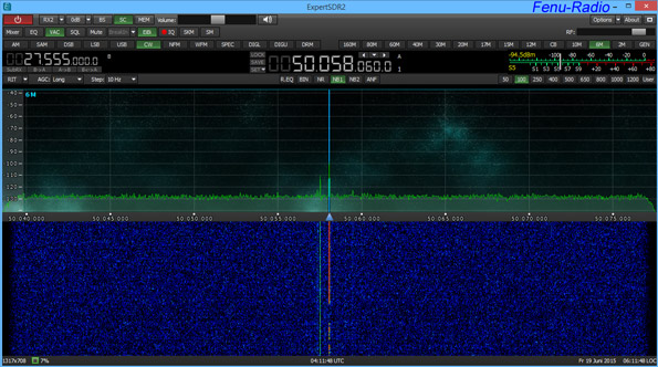
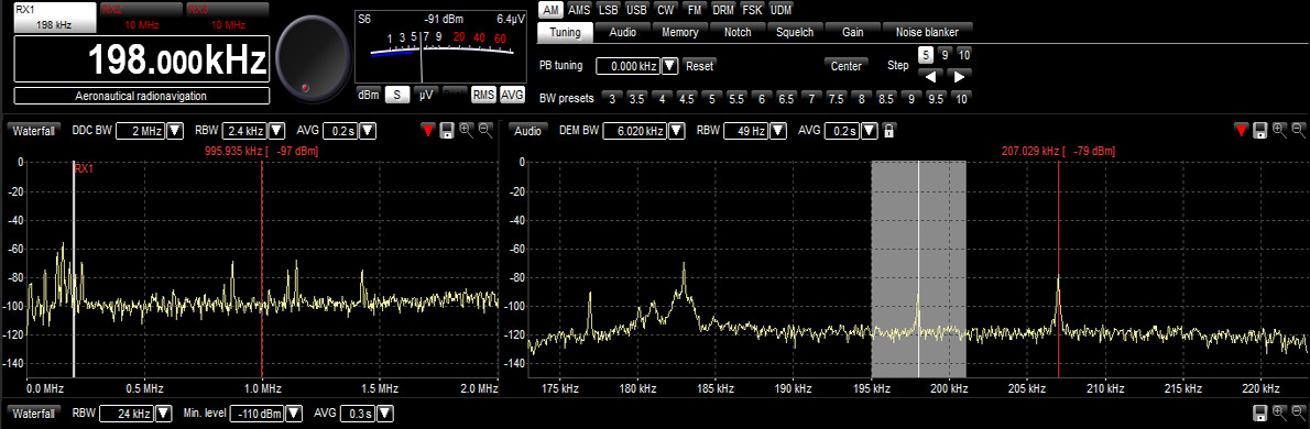
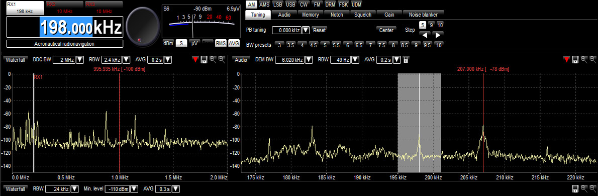
Thanks to Bonito for the diagrams How does it work? During several weeks, I compared the ML052 with the broad-band ML200. I wanted to find out how both the loop amplifiers differed. In order to demonstrate this, I took some screenshots which show what the basic noise level and the important signal/noise ratio (SNR) of both amplifiers fastened to the same loop were like. The loop which I used had a circumference of approx. 8m and an area of almost 4 square meters. As we all know, the frequency bands are subject to fading and other interferences and so the screenshots are actually snapshots of a particular moment and are no indication of an over-all performance. If I wanted to make the comparison as exact as possible, I would have to change the loop- amplifiers as quickly as possible. Because the differences were so small, I did not take any screenshots of the upper frequencies. 23.4KHz DH038 ↓
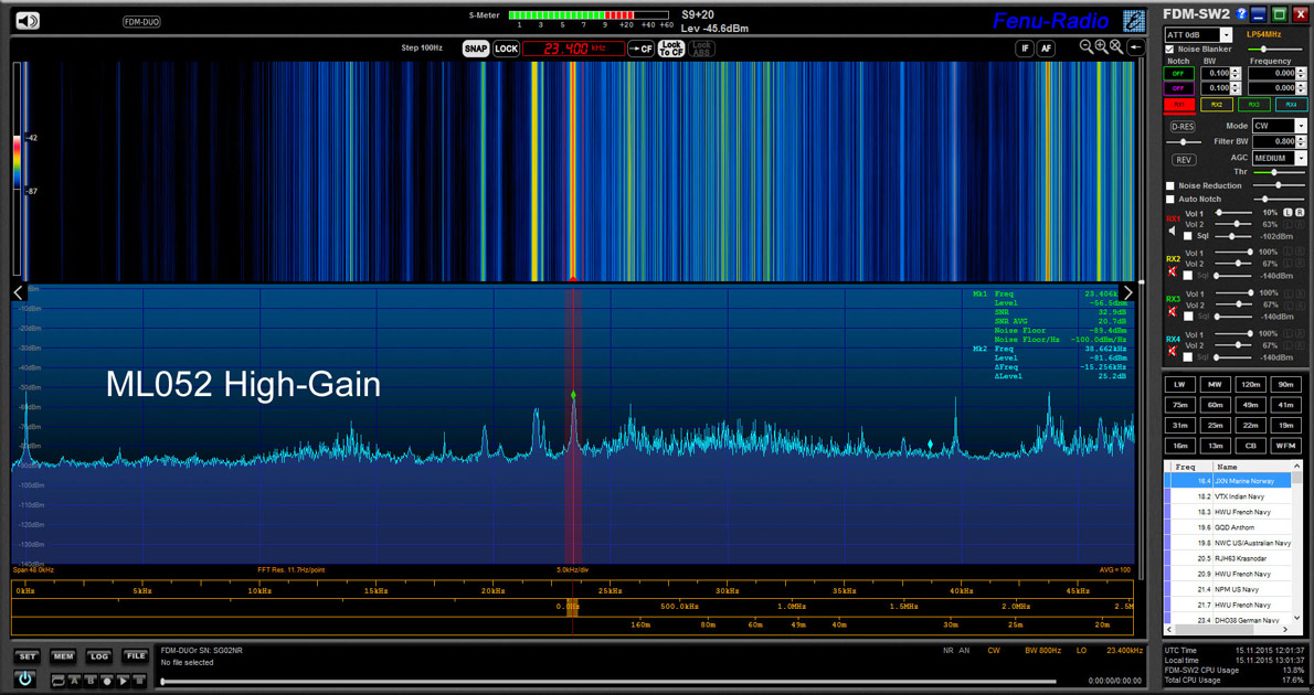
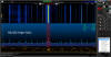
198KHz BBC ↓
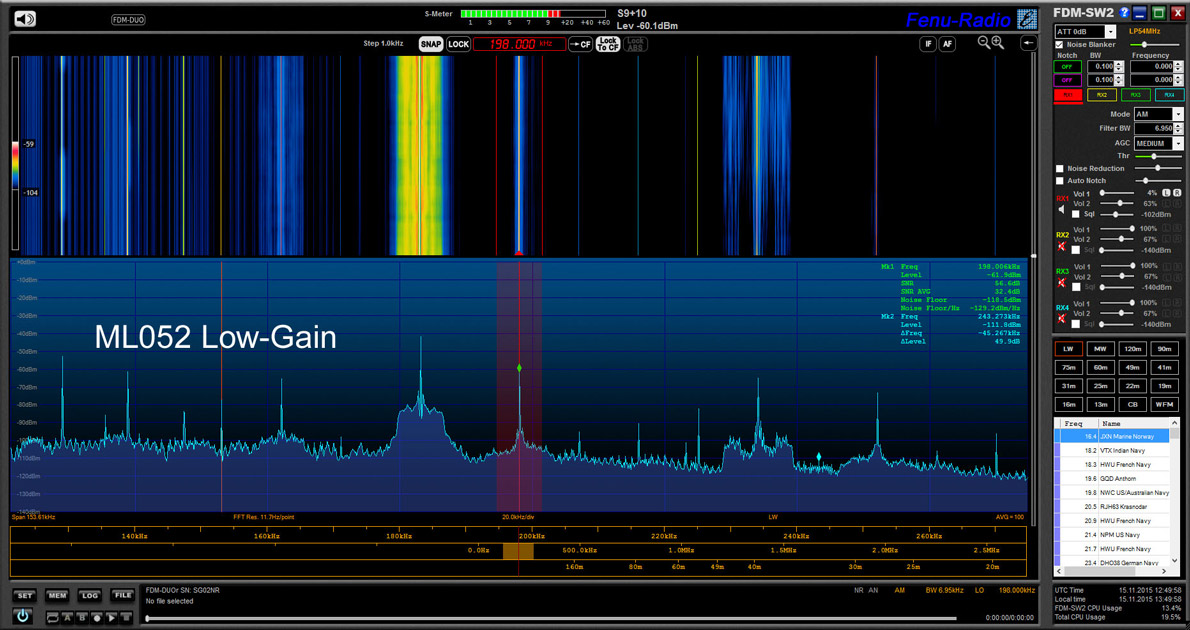
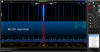
1278KHz France Bleu ↓
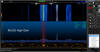
5800KHz unknown Station ↓
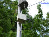
9655KHz Rumänien ↓ [photogallery/photo00031446/real.htm]17490KHz China Radio ↓
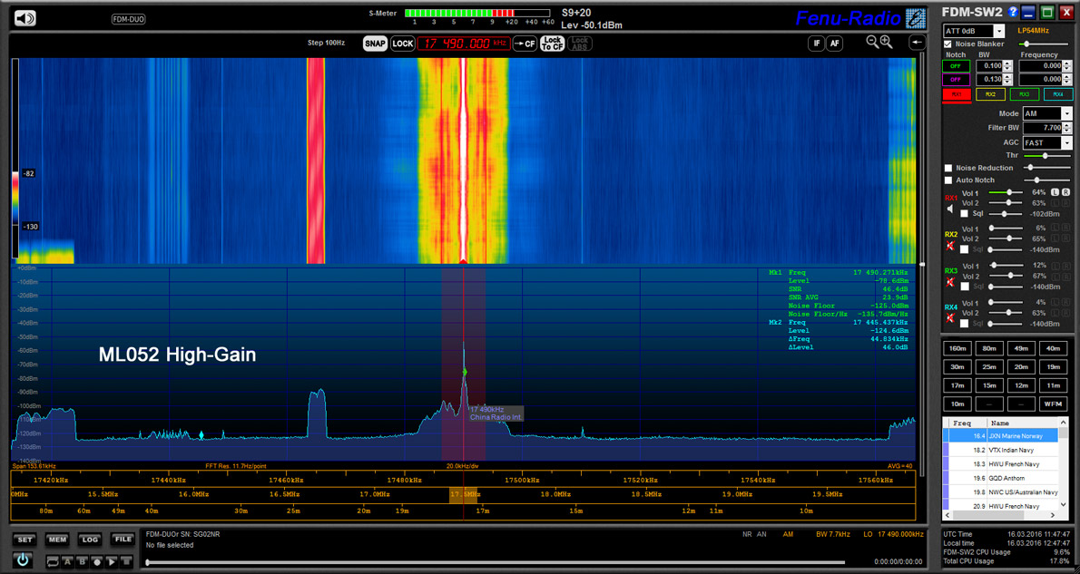
Conclusion The noise level of the ML052 is higher than the one of the ML200 by 2-3dB, but that is of no importance because amplification is higher by 2-3dB as well. As a result, the signal/noise ratio (SNR) is the same as for the ML200. These differences are not noticeable at all and could only be seen in the spectrum. Reception of the ML052 is on par with the ML200. The ML052 has a FM blocking-filter and is the antenna of chopice if you live in densely populated urban areas or close to a strong FM station. Many thanks to NTi (Mr. Rudolf Ille) for lending me the ML052. posted: 6.04.2016
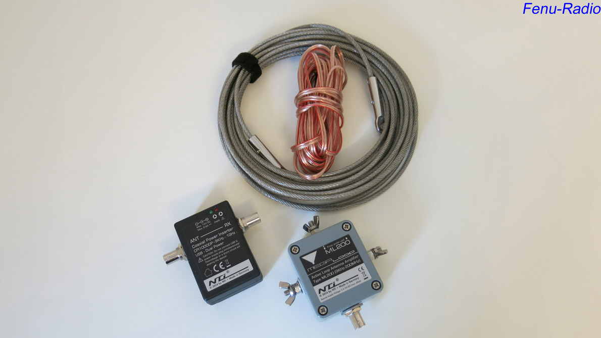
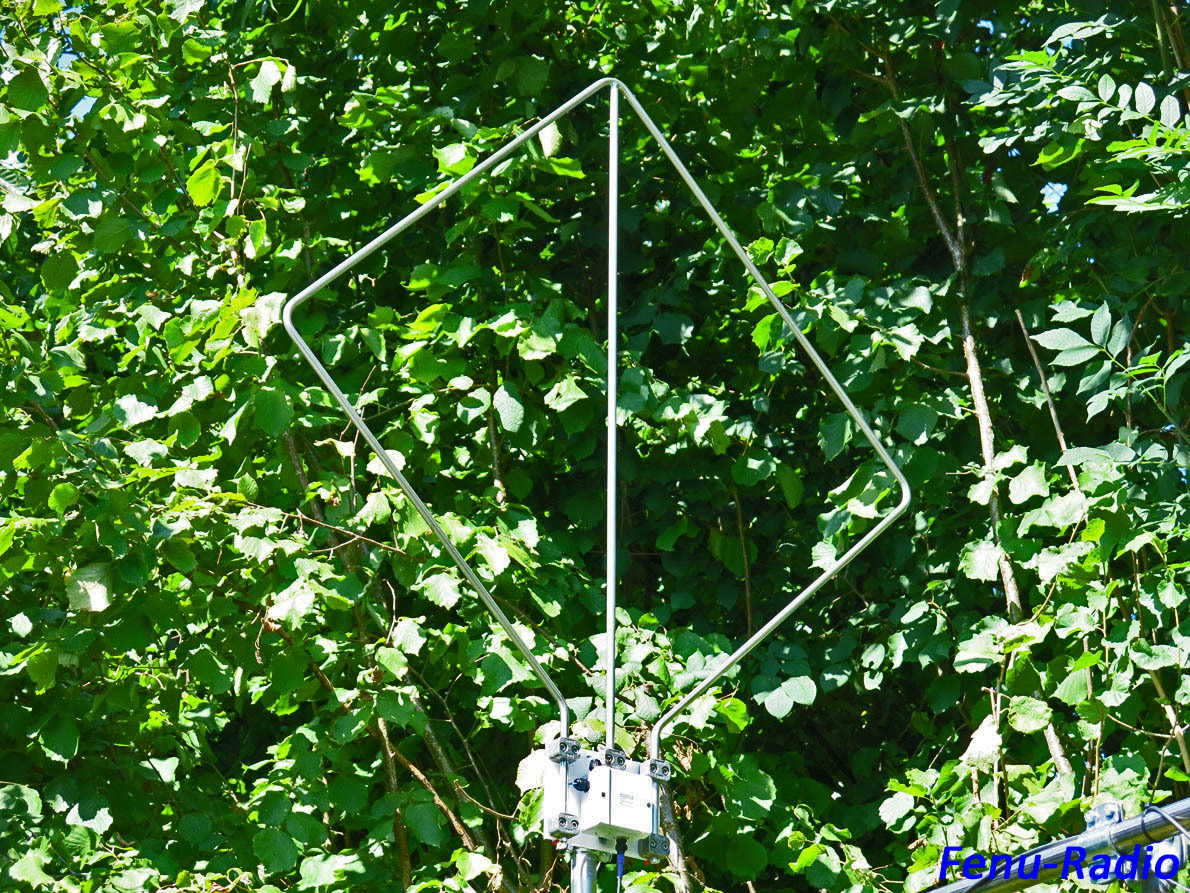
After I had gained some good experiences with the electric field (E-field) active antenna NTi MegaActiv, I also ordered the magnetic (H-field) MegaLoop ML200. Mr. For testing purposes, Rudolf Ille sent me the latest version with improved large signal immunity. The ML200 is said to have an IP3 of +40dBm and an IP2 of +85dBm, which are remarkable values as such and set expectations even a notch higher. The ML200 has the same enclosure as the MegActiv, i.e., it's rather compact and watertight. The supplied antenna loop is made of copper, has a circumference of 5 m and is insulated. Supplied is also a flexible power inserter CPI1000DP, which can be powered by USB with 5V or via a barrel jack (5-15V max.). For this test, I powered the ML200 with the barrel jack and 13.8V. Additionally, you will be supplied with a 10 m antenna loop made of stainless steel.
The ML200 is made for portable operation. It is not a fixed and rigid construction such as the Wellbrook ALA1530, but the loop is put temporarily over a bush or on a tree. If you want to use this antenna for stationary operation, you would have to think of some kind of permanent mounting. You could fasten it to a wall or a wooden construction. The antenna should be erected free and unobstructed so it can achieve its potential. Walls and wet wooden mounting constructions would impede reception, though. In order to have an optimal surrounding for the ML200, I built a stable suspension made of bamboo and stainless steel. This is a very trendy combination and makes for a nice look as well. I constructed this suspension in such a way that it can be easily dissembled and transported and so this antenna can be used as a portable and at DX-Camps.
.jpg)
The ML200 is made for the 9kHz - 170MHz range which is a rather wide range for a magnetic loop. The antenna's electronics offer selectable amplification (+0dB/-9dB) to adjust it to different levels. This is done by jumpers. To access these, you have to open the enclosure. Next to the green jumper, there is also a gas discharger which protects the antenna from overloads. Additionally, you will find a ground connector (brown cable) which can be attached to the ground on the enclosure. All outside screws are made of stainless steel. ↓
Testing the ML200 with a 5m loop Thanks to my T-construction, erecting the antenna was quickly done. I compared the ML200 to a cross loop/RLA4C antenna, which was fastened on the same mast with a 2m-distance. The RLA4C renders high levels with an excellent SNR. I operated the ML200 with the 5m copper loop. It is recommended to experiment with the selectable amplification of the ML200. I could operate the ML200 with the High-Gain-Jumper position. The +0dB (High Gain) produced no noticeable noise. In a direct comparison with the cross loop, which of course was always pointed into same receive direction, the ML200 showed strong reception signal in the VLF-range. Below 100kHz, the cross loop was definitely at a disadvantage. From 100kHz to approx. 15MHz, it was the other way around and the ML200 was not as good as the cross loop. Similar to the cross loop, the ML200 has an excellent SNR, but rendered less signal level, the difference being approx. 6dB. These few dBs can be decisive, however, when doing 'hardcore' Dxing. Operation with the 10m stainless steel loop Spoilt by the cross loop and the BigLoop, which I owned in the past, I exclusively use highly effective antennas these days, and so I was anxious to test the ML200 with the 10m stainless steel loop. This loop produces considerably higher levels out of the Ml200. Starting again at the VLF-range, I compared the same frequencies one more time. The ML200 with its 10m loop produced almost frighteningly strong signals. The ML200 puts the already effective Mini-Whip types at a considerable disadvantage. I also experimented with the "Gain-Jumper" . In the High-Gain position, there was no increased noise and the SNR remained very good, too. On long- and medium wave, both the antennas had a neck -and- neck -race. There were no relevant differences to be noticed. Both antennas worked on the highest level. Up to approx. 15MHz, there is no difference between the cross loop/RLA4C and the ML200. The ML200 produced a slightly stronger signal. Starting with 15MHz, the ML200 keeps its level and remains very efficient up to the 10m-band, whereas the cross loop/RLA4C loses some of its efficiency. In the 11m and 10m-bands, the ML200 is excellent. The important SNR was also convincing on the higher bands.
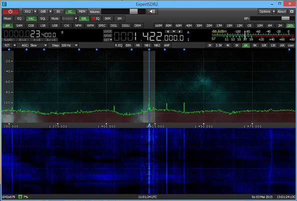
On the long and medium wave both antennas in a neck and neck race. Relevant differences were no noted . Both antennas play here at the highest level! ↓
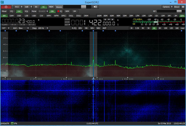
Up to approx. 15MHz, there is no difference between the cross loop/RLA4C and the ML200. The ML200 produced a slightly stronger signal.↓
Starting with 15MHz, the ML200 keeps its level and remains very efficient up to the 10m-band, whereas the cross loop/RLA4C loses some of its efficiency. In the 11m and 10m-bands, the ML200 is excellent. The important SNR was also convincing on the higher bands.
Also in the 6m band, the differences are clearly noticeable.↓
The electronics of the RLA4C are only designed for up to 55MHz, but it receives the FM-band reasonably well, too.↓
Conclusion: Over the years, I have had a couple of good antennas which almost left nothing to be desired, especially the Reuter Loop electronics RLA1B to RLA4C. Together with my home-brew loops, they produced excellent results. But the NTi MegaLoop ML200 is in a league of its own! Across the complete frequency spectrum, this antenna produced at least the same results as the cross loop/RLA4C. I was especially surprised by the receive qualities in the VLF range. No other antenna produced such strong signals with an excellent SNR as the ML200. It also convinced me as far as the upper frequencies are concerned. After a test period of almost two months, I have found a new winner: The NTi MegaLoopML200! Many thanks to Mr. Rudolf Ille for putting the ML200 at my disposal. Die ML200 are available in the Hamradio-Shop. A tip fort erecting the antenna by Hans Joerg, DE2HJW Inspired by your construction for the MegaLoop, I gave it a try. But with installation pipes for cable wiring and clips for stabilization. The loop has a circumference of 10m. Construction on a 12m "van der Ley Mast". The booms are fastened to the mast with cable tie, which seems to be stable enough for a light weight. posted 20.06.2015
.jpg)
Although more and more radio stations are switched off for good, there seems to be a revival of the market for long-, medium and shortwave antennas. Especially small active antennas, the so-called mini-whips and their further developments, are in the centre of attention. That is not surprising because these tiny E-field antennas, hardly longer than 30 cm, render an almost unbelievable reception quality. Additionally, there is the attractive value for money. The whips made by the NTi & Bonito Company belong to this type of antennas. Bonito and NTi work closely together and are constantly working on making these small and inconspicuous antennas even better. Mr. Rudolf Ille, the owner of the NTi Company in Southern Germany close to the Swiss border, is responsible for the development and the production of the whips. Mr. Dennis Walter, the owner of Bonito, conducts the tests of the products and helps Rudolf with his ideas and proposals. But also ideas and criticisms from customers are welcome, and whenever possible they are implemented. Dennis Walter visits DX-Camps regularly to compare the antennas with other products. The results are then analyzed and made use of for further improvements. That is really customer-friendly!! When the antennas are ready for the market, Bonito is responsible for distribution. It is often advantageous, if antennas are tested by people not involved in the production and distribution of the products. Only then you can find out how the antennas work when they are operated in a different place and with different receivers. Additionally, there should be comparisons with other types of antennas because you would like to know in which category of antennas a specific type of antenna belongs. To find this out, I was sent a MegActiv before the market launch.
.jpg)
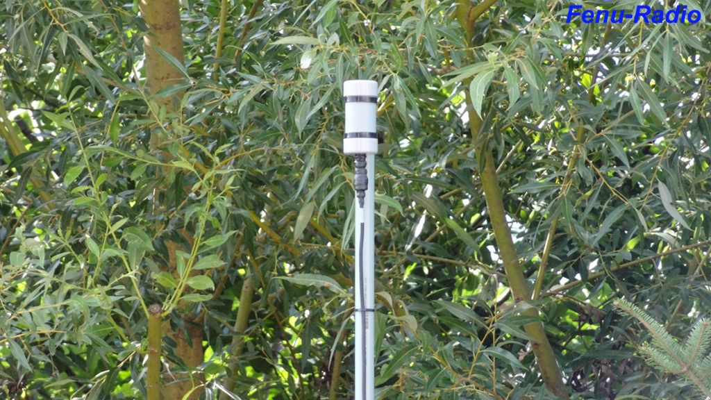
The MegActiv 305 comes with a 18cm long receiving element made of rubber and a power inserter You can also order a mast clamp made of stainless steel, an antenna cable and additional accessories. The watertight enclosure is made of plastic and seems to be stable enough. Because of its antenna adapter, also made of stainless steel, and which has a M6 thread, the antenna is flexible and is ready for experiments. You can also experiment with different lengths of the receiving element. Special attention must be paid to the power inserter. Besides the normal DC power connector, it also has a USB port for power supply and so you can power the antenna with either a PC/Notebook or a 5V-power bank. This makes for two options regarding the power supply of the antenna. The voltage of the MA305 is between 5 - 15V max. My recommendation: It is best to use a 13.8V stabilized power supply. Switching power supplies are often of inferior quality and cause interference. Because of its low power consumption of max. 40mA, you can operate the MA305 with a 5600mAh for days on end and it makes this antenna very flexible to use. Especially for portable operation or in case of faulty electrical lines at home, this solution really pays off. A real novelty!
.jpg)
Installation of the antenna is really easy. Screw the mast clamp on and start operation. I fastened the antenna to a 7m-meter aluminum mast. For comparison, I used a Dressler ARA30 which was modified for the lower frequencies and starts reception at 20kHz. For receivers I used the Perseus SDR and the Colibri SDR. Starting with the VLF-frequencies and up to approx. 1000kHz, the MA 305 was the clear winner. The ARA 30 produced vey high levels, but the SNR (signal-noise ratio) was not as good as it should have been. Compared to the MA305, the basic noise level was always higher by 10-12dB. Here, the MA305 showed its strength: best SNR with an equal noise level. In the lower frequency ranges, weak stations could be heard better and more pleasant with the MA305. On medium, wave, the difference between the two antennas became smaller, but the ARA 30 was not the winner here. Compared to the MA305, the noise level was higher by approx. 10dB but it still could not surpass the good SNR of the MA305. Additionally, there were mixer products coming from long wave frequencies. Because of its good SNR, the MA 305 is the winner again on medium wave.
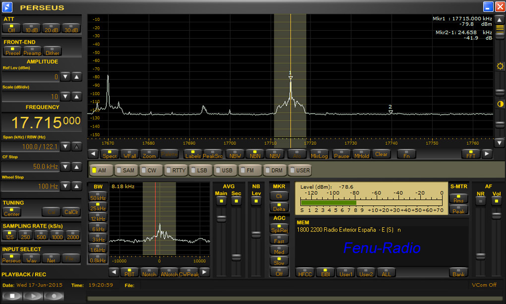
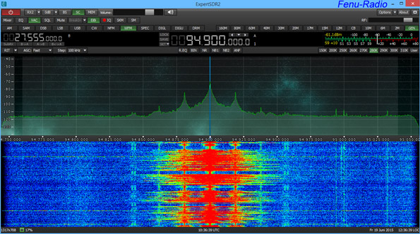
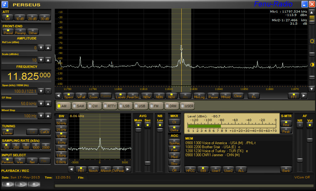
And so it continued on shortwave. On the lower shortwave frequencies up to approx. 4 MHz, the MA305 was better again. The ARA30 had a higher basic noise level, which made intelligibility worse. Starting at ca. 4 MHz the picture changed somewhat. Both antennas showed the same receiving qualities. Up to approx. 15 MHz both antennas worked equally well and the longer receiving element of the ARA 30 showed its properties. Some stations could be heard a little better. There still was an increased background noise and the MA 305 lost some of its reception. With the higher frequencies up to the 10m-band, the ARA 30 proved to be better and better. I made use of the flexibility of the MA 305 and tried to improve reception by adding a home-made 1m long antenna element made of a 6mm stainless steel pipe. On the higher frequencies, a higher signal level was noticeable by ca. 10dBm and the MA 305 came close to the ARA 30. Here you can see the signal/noise level of the NTi MegActiv between basic noise level (1) and signal peak (2). SNR = 40.8dB The bigger the difference between basic noise level and signal peak the better the SNR.
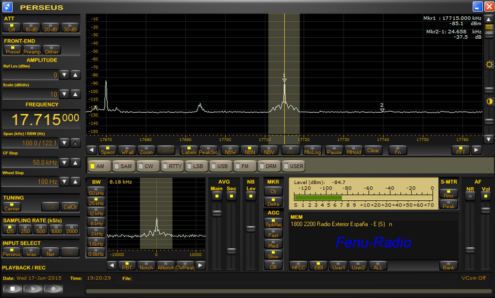
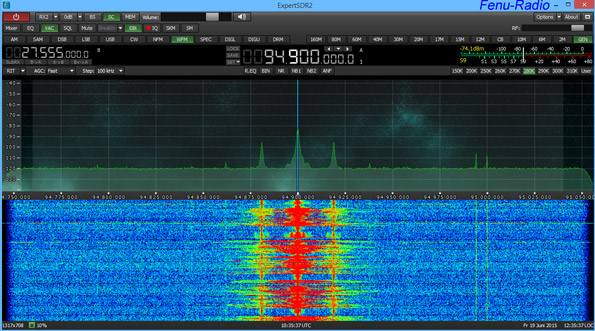
Here you can see the signal/noise level of the ARA 30 between basic noise level (1) and signal peak (2) SNR = 31.5 dB.
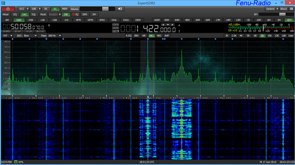
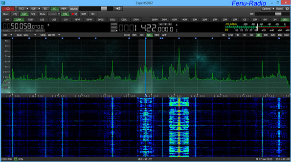
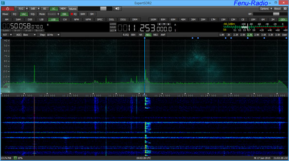
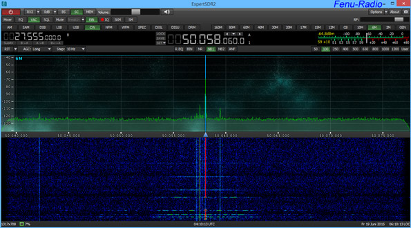
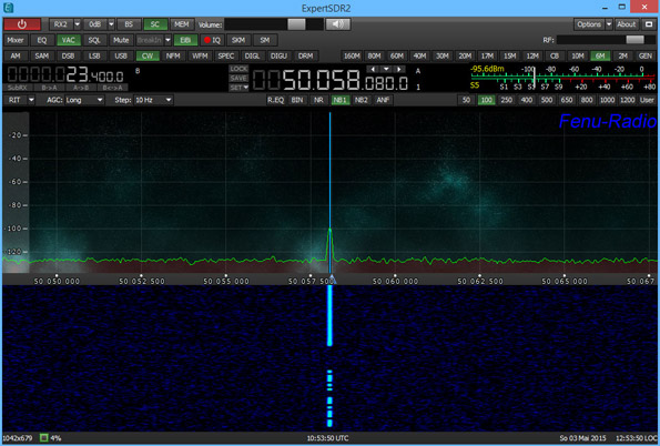
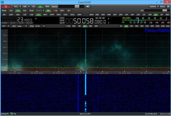
It is a well- known fact that the height of a mini-antenna is of great importance. In order to test the MA 305 with a different height, I shortened the mast to three meters and ran tests throughout the whole frequency ranges and I came across the following results: On the lower frequencies, there was hardly any change. With increasing frequencies, the levels were higher by 10dBm. Possibly, there were resonance frequencies caused by the cable and which attenuated reception. I used the longer receiving element once again and compared both antennas at a height of approx. 3m above ground and now the MA 305 was on par with the ARA 30. On the higher frequencies, both antennas worked equally well, although the MA 305 had a slightly weaker level but because of its better SNR, the MA 305 could compete with the ARA 30. The MA 305 works on frequencies up to 300 Mhz. With the ICOM IC-R9500 and the Colibri-SDR, I could run tests on the higher frequencies. For these tests, I used the Dressler ARA500 which is made for these ranges. In the 6m-band on 50.058 MHz the amateur radio beacon from Säntis (CH) could be heard with both antennas equally well and with identical signal strength. ↓
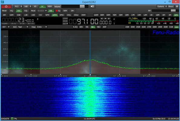
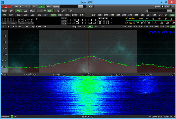
The MA 305 is also suitable for the FM-band and is on par with the ARA 500. Only in case of weaker stations, the ARA 500 is better because it is tailored for these frequencies.↓
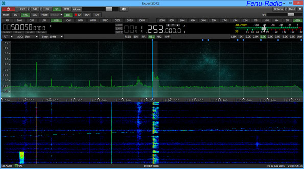
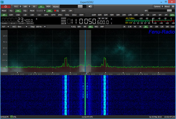
The last signal which could be received satisfactorily was the aeronautical beacon Zurich-East. Both antennas were almost identical. Because of lack of signals, I couldn't run any tests on the 2m amateur radio band.↓
Conclusion: The NTi MegActiv is a small receiving antenna with excellent reception results. Erecting the antenna proved to be without any problems similar to the Boni-Whip. Despite its small size, the antenna receives signals from VLF to the FM-bands very well. When installed correctly, it offers an unbeatable SNR! What is really important when using this type of antenna is the height. The MA 305 works best, when it is between 2 and four meters above ground. If it is erected too high, there may be resonance frequencies caused by the cable. Another asset is the flexibility of the antenna. You can use longer receiving elements to improve reception. An alternative to the rubber receiving element is a 1m-long rod which increased the level at the same SNR. My thanks go to Dennis Walter for lending the MegActiv. The MegActiv can be ordered at the Hamradio-Shop.posted 25.05.2015
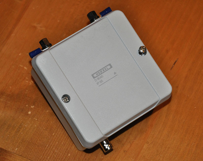
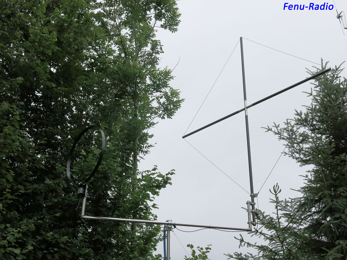
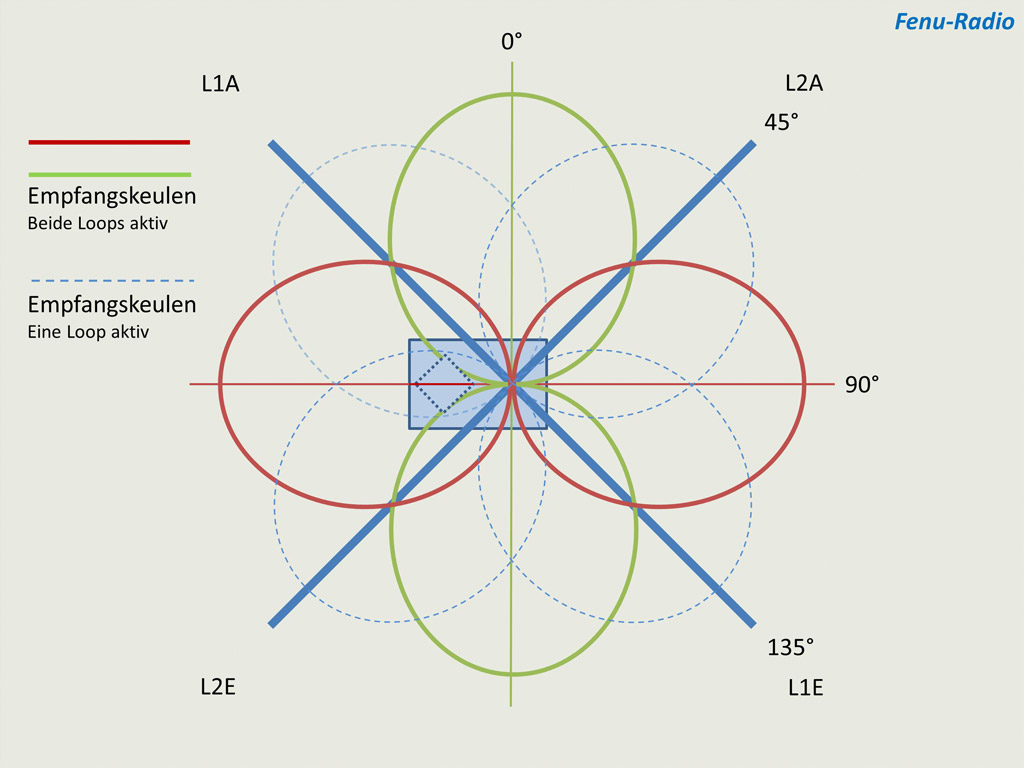
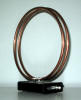
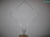
Inspired by the new cross loop RLA3B by the Reuter Electronic company, whose receive direction can be changed electronically in 45° steps, I started to build a cross loop double the size of the RLA3B. My cross loop with a diameter of 120cm is of a quality which meets the highest expectations. Both loops are 40x4mm and aluminum profile. In order to achieve a round loop, the profiles had to be rolled. The rod in the middle, which serves a supporting rod and as a grounding device, is made of 18x1mm stainless steel to give the antenna more stability. Aluminum would have been too weak for the rod. The antenna base plate is a dye-cast aluminum housing made by Rittal and is 160x160x90mm and watertight. This case houses the RLA3B electronics. No wonder then that the antenna weighs 6.3Kg.
.jpg)
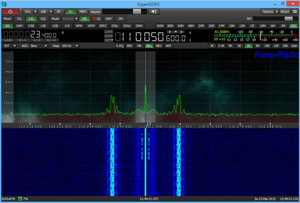
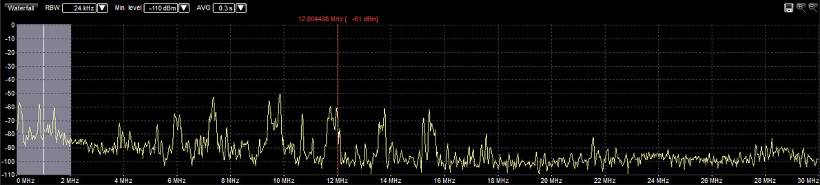
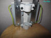
In the past, the Reuter company assisted me with my experiments and also this time. Mr Reuter put the complete electronics and the antenna controls at my disposal. After some mechanical alterations of the circuit board, the first experiments could start. As already mentioned, the same electronic components "RLA3B" were used for my cross loop which are also made use of for the 60cm loop made by Reuter. I compared this antenna to the Fenu-BigLoop/RLA1B and the Mini-Whip. When directly pointed to the 23.4 KHz military station DH038, the cross loop rendered an incredible signal. The S-meter of the Perseus pointed to S9+30dBm. Die Mini-Whip which is said to be unbeatable for this frequency range, "only" produced a 9+10dBm signal. Then on to the long wave section of the radio. DLF on 153Khz( shut down in the meantime) caused full scale reading of the meter: S9+70dBm. The Mini-Whip showed the usual S9+30dBm. The BigLoop rendered a somewhat weaker signal in this frequency range, but had the better SNR. And here started a problem which I had been afraid of from the start. The cross loop with its 120cm diameter simply produced too strong a signal for the electronics of the RLA3B. And so on to the medium wave range. Soon it became clear that the cross loop was simply oversized. The signals were a lot more stronger than those rendered by the other two antennas. RTL Radio on 1440 KHz (shut down in the meantime) had a S9+10dBm signal during the daytime compared to a normal signal of around S5-7. Interestingly enough, the SNR was about the same as the one of the BigLoop. Stations, which normally could only be received with difficulty during daytime, could suddenly be received well, which is good on the one hand but on the other, something had to be wrong. And shortwave! The cross loop easily surpassed the other two antennas. It received the stations with an unusual strength and good SNR. But it did not last long. With evening time approaching, the signals became stronger and some receivers and antenna amplifiers have the tendency to overmodulate. And that was also true in the case of the antenna electronics of the RLA3B. It took me several days to understand the performance of the RLA3B. The overmodulation occurred mainly between 19 - 19.7 MHz. It became clear that these were caused by harmonic frequencies of strong broadcast stations in the 31m band. Especially Radio Romania on 9780 KHz came in with a bang of S9+60dBm. The BigLoop rendered about S9+40dBm. It was no wonder then that the electronics suffered from signals which were simply too strong. The loop was basically too big. To bring the situation under control, you can make the loop smaller. But that was out of the question. My aim was to build a high-performance cross loop.
.jpg)
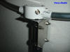
I contacted Mr. Reuter to get technical advice. The condition was that the loop shouldn't be made any smaller. Mr. Reuter advised me to experiment with various resistors at the input of the amplifier to attenuate the high levels rendered by the loop. After two weeks I had the correct values. At each input of the loop electronics I installed a 7 Ohm metal film resistor which resulted in 14 Ohm. The levels came noticeable down but not equally well for each frequency range. And the harmonics were still there, nonetheless. After some further experiments with chokes it became clear that this was not the solution. I had to get an amplifier board with less amplification and so Mr. Reuter made a new board with 10dB less amplification which after three weeks was put into practice. The level stayed about the same but the harmonics were weaker. Not good enough! After some weeks a new, improved board arrived, the RLA4A. Once again, a prototype with improved electronics. I tested the RLA4A for a couple of weeks. All of this took a lot of time and patience. Not every day was the same. Sometimes the signals were very strong and then again they weren't. But it paid off to invest some time with experiments. The new RLA4A worked clearly better. For several weeks I hardly noticed the harmonics on the 19MHz and did not see them in the spectrum, either. So I was finally on my way of having a high-performance loop. Now the cross loop was ready for the endurance test. I took it with me to the DX-camp in Holzerbachtal near Solingen. The antenna could be tested by everybody present. Unfortunately, most people were busy logging stations and only three DXers tried the loop. Compared to the antennas in use there, the cross loop proved itself to be a little better in most instances. It was the only antenna that could receive a NDB beacon from the USA. At the camp, there were two HDLA3s, a tuned HDLA3 with 5.5m circumference, a ALA 1530 and the BigLoop. The electronic direction switching was very conducive to reception. Without any delay, the receiving direction could be changed in 45° steps which was very practical to null out interferences in the higher frequency bands. As I used the cross loop most of the time, I also noticed some negative aspects. A nearby FM transmitter caused interferences when listening to shortwave stations and this suggested a suboptimal FM choke. The other antennas showed no such interferences. There still was room for improvement! After the DX-camp I informed Mr Reuter about the results. Based on this experience, there is an improved version of the antenna electronics available, the RLA4B with a little less gain and all other things being equal. After some days, I can say that the long and arduous way was worth it. Now I have a cross loop with an ultra-fast change of direction. The antenna leaves nothing to be desired. In the meantime, the harmonics around 19MHz showed up again but they are hardly noticeable and they are at frequencies where nothing interesting is to be heard, anyway. Meanwhile, the RLA3B with two amplifier stages is available on request at the Reuter Elektronik Company. posted 04.02.2015
The Reuter Elektronik company is well-known for manufacturing high-quality receivers. For some time, this small company based in East Germany has also been building high-quality antennas. In the middle of 2013, Heiko Priess tested the preceding model "RLA1" and attested to its good receiving qualities. I also made some experiences with the antenna electronics/circuit board RLA1B, which I had combined with my homebrew loop antenna "Fenu-BigLoop". This combination rendered very good results and during a DX-camp, it proved to be an efficient and low-noise antenna. Now Reuter's is launching a newly-developed indoor antenna, which can electronically be pointed to the receive direction. The RLA3A is a small table loop with two crossing loops, i.e. a crossed loop antenna. The loops are in the shape of an octagon and have a diameter of 36cm. They are made of copper-coated glass fiber. For protection, it is also powder-coated. In the middle of the loop, there is additional grounding which suppresses electric interferences even more. The loops are screwed onto a small aluminum case which houses the electronics. The whole antenna is superbly finished, only the best components were used. The labeling is not glued or painted, it is engraved. The RLA3A can either be operated with the control unit "RSW1A" or without. If it is used without the control unit, the receive direction can be changed by 90° with a switch so you do not have to do that manually. If you use the control unit, you can change the receive direction in 45° steps which comes very close to a loop turned by the operator. This electronic change of receive direction is a novelty for indoor antennas. The change of receive direction is done by voltage variation and is indicated by four red LEDs on the controller. If you use the controller, the RL3A can be operated remotely in an other room or in the attic and so interferences can be avoided. That is quite an advantage! The usual antenna cable RG58 between controller and antenna should not be longer than 20m and according to Mr. Reuter, 30m should be possible with Aircell 5 cable so quite a distance can be bridged. If the cable is too long, there will be a drop in voltage and changing the receive direction becomes impossible.
.jpg)
Reception I compared the RLA3A to the Grahn GS5-SE/ML3 which I received at the same time. Unfortunately, I could not compare both antennas indoors because strong interferences impeded reception too much and so I escaped into the garden. Conditions were much better there. Although the Grahn antenna follows a different concept, I compared it to the RLA3A nonetheless. The RL3A is a broadband loop. The Grahn on the other hand is a tunable narrow band system which has to be retuned after bigger frequency changes. But after all, both antennas are indoor antennas. For radios I used the Reuter RDR50C2, AOR AR3030, Tecsun PL-880 and the Perseus SDR receiver. As the RLA3A is a broadband loop and renders strong signals, the PL-880 and the AR3030 had some trouble with the broad spectrum of signals. During daytime, there were some intermodulation effects within and without the broadcast radio bands. To solve this problem, the attenuators of these radios had to be activated. When I used the narrow band Grahn antenna with these radios, there were no strong signal effects. All of this makes it clear that the RL3A is not suitable for pocket radios and receivers without good strong signal immunity. On the other hand, there were no problems with the Reuter RDR50C2 and the Perseus. Considering its size, the RL3A's reception was very good and almost noise-free. Starting at 23,4 KHz up to almost the 10m amateur radio band, the Reuter antenna rendered strong signals which were mostly stronger than the Grahn's. But signal level is not everything, as we all know. The magic word is "Signal/Noise Ratio", SNR in short. In this respect, the Grahn was almost the winner in each instance. But not on all frequencies. On the lower frequencies, the Grahn antenna was a tiny bit more noise-free. But on the upper frequencies, the RL3A caught up and surpassed the Grahn. But all in all, the differences were not so great and were only noticeable when you listened very carefully and closely. Whatever was received with the RLA3A could also be received with the Grahn and the other way around. The electronic change of receive direction worked perfectly and on the higher frequencies just as well. It was possible to null out interferences and make the signals more readable. Conclusion: The RLA3A made a good impression in addition to the workmanship typical of the Reuter company. Really top class! If you operate the antenna with the optional controller RSW1A, you can remotely control the antenna, a feature which has been unheard of so far. But where there is light, there is also shadow! I noticed two things which could be improved. The antenna is somewhat unsteady on its base plate because the mass center is rather high. It tips over relatively easily when you push it by accident. The other problem is of a more cosmetic nature. The DC jacks of the antenna and of the controller are both on the control side and should be on the back because the DC cable is always in the way. I contacted the manufacturer and he promised to look into it. After all, it is also a question of cost. I also missed a battery compartment which would make outdoor operation a lot easier. More info under: Reuter Elektronik Many thanks to Burkhard Reuter for lending me the RLA3A posted 23.09.2014
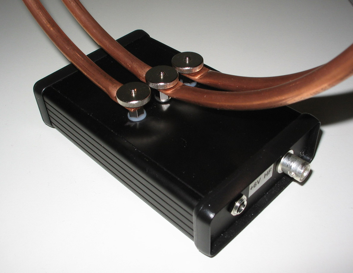
By Heiko PriessSome weeks ago, the Burkhard Reuter company, which is well-known for its high-quality and professional receivers announced its own newly-developed electronics as a basis for a low-noise and broad band loop, which was to be offered as a kit and ready-assembled as well. What about this antenna then? The aim is ambitious: A broadband, compact and universally usable antenna with a low as possible noise level for the RDR receivers of the Reuter company and other receivers as well. I was delivered an antenna of the first series, complete with the optional 22cm double loop in the form of a copper pipe. All of it made a stable and high-quality impression, and the small size is astonishing. The loop, which is fastened to the enclosure with three knurled nuts, can be detached easily for transport, but all in all it makes a very stable impression. However, this version is only one of many possible ones of how the electronics can be made used of. You can use the antenna indoors with e.g. the 22cm loop, which is available in case you do not want to experiment yourself. The loop could also be used as an outdoor antenna, in this case the user has to build a watertight construction because normally the antenna is made for only a short mobile outdoor installation. This model can be powered either with a 5-6V DC power supply or with batteries for mobile use, both of which are not included. You will find a standardized connector with central polarization and the positive pole in the middle. According to the manufacturer, power consumption is about 150mA ; Based on my measurements, it is a little less, actually. It is also possible to power the antenna via remote power supply with max. 6V. A conventional power inserter would be suitable. According to the manufacturer, it is planed to offer the RLA with jumpers which make various levels of amplification possible: One only for indoor or travel operation for a somewhat higher amplification of the loop and the other for permanent installation of bigger loops.
The version at hand is the one with less amplification which should be operated with a bigger loop to show what it can do. That's why I also included tests run with my own 60cm loop. According to the manufacturer the low noise level can be achieved by even less noise-free transistors and a different input circuit with -compared to the HDLA- unusual voltage of 6V. Contrary what was said in regards to the prototype, a higher voltage cannot be used. Maybe it was not always justified, but now and again I compared the RLA1 to my HDLA3, which I only use indoors. This might not have been always fair, the results were convincing, nonetheless. Occasionally, I also used a Sony AN-1 and a Grahn GS5-SE with its ML3-Loop for comparison. Besides the Excalibur SDR, I mainly used an Icom IC-R75 and other receivers as well. Now, how does the base unit work with different loops? Using the 22cm double loop the levels above medium wave were considerably lower than the ones that the HDLA produced with a 30cm loop, but with a 60cm loop the RLA really gets going and renders enormous signal levels comparable with those produced by the HDLA. As you can see in the following screen shots, the results of the RLA are relatively similar, up to 2 MHz the signals are even above the HDLA's. Signal path of the HDLA with a 30cm loop ↓ 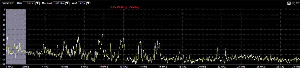
Signal path of the RLA1 with a 60cm loop ↓
For lower noise levels, the best compromise seems to be the small loop, which definitely has a better S/N ratio than the HDLA, especially in the VLF, LW, and MW range. Starting at about 2 MHz, the HDLA is getting better and better, but with less noise, the RLA still renders a comparable S/N ratio. A few examples: The British signal station on 60kHz was noticeable in the noise using the HDLA around noon and was also audible; the RLA with its 22cm loop, however, produced clear signals. The same could be observed when tuning in the frequency 147.3kHz, a RTTY station of the German Weather Service: the HDLA suffered from more noise than the RLA. The difference between the two antennas can be seen nicely on 198 kHz. With the RLA, I could follow the program a lot better. The signal was not necessarily stronger than the HDLA's, but the noise was considerably lower. HDLA with a 30cm loop: BBC noticeably noisy, but audible ↓
RLA1 with a 22cm loop: BBC clearly audible ↓
There is a piece of news that I received: The diameter of the double loop will be enlarged to approx. 30cm. in order to achieve the optimum of size vs. signals strength with the planned amplification . For bigger loops (home-made) the electronic will be reduced to less amplification in order to get the best noise level.In some respects, the base unit at hand with the serial number 0006 is currently superior to the HDLA in that it does not necessarily render stronger signals ( sometimes even weaker ones) but that it has considerably less noise which is decisive for a the intelligibility of a signal.
Conclusion at present The RLA1 renders really good results. The originally supplied 22cm copper double loop is rather a minimum and is only good for VLF-MW frequencies. Above these frequencies, the levels are considerably lower than those rendered by the HDLA so that many signals in the higher shortwave range are weaker when compared with the HDLA. On the other hand, the signals are still stronger than those received with a broadband antenna such as the Sony AN-1. As far as I see it, the results are acceptable. Compared to a narrow band Grahn antenna- which is in the same price category - the RLA1 is even at an advantage. Just to mention the Grahn GS5-SE with its ML3-Loop: when optimally tuned, the Grahn renders the same intelligibility and did almost as well. In conclusion, things are just as the manufacturer says. He does not necessarily recommend big loops because the signal/noise ratio does not get better when bigger loops are used, unless you live in a really noise-free area. The noticeable weaker performance with copper double-loops in the higher shortwave range is due to its construction. On the other hand, however, the RLA1 works really well in the lower frequency ranges and this because of its low input resistance and the antenna can even beat the very good HDLA. If you are looking for a broadband antenna which can be used as a mobile antenna you should take the RLA1 with a smaller loop into consideration. If you have plans for a stationary antenna, the size of the loop and its location is of utmost importance. If you want to work with bigger loops, the RLA 1 becomes increasingly less recommendable because then its main advantage, i.e. relatively noise-free reception-does not really come into play. With a 6ocm loop, you will receiver strong signals with the noise level being acceptable. With bigger loops, however, the advantages of the RLA1 are increasingly lost. The RLA 1 is available at its manufacturer, the Reuter company, either as an assembled board (150,-€) or as ready-made device (290,-€). Thanks a lot to Heiko Priess for this detailed report. posted at 10.05.2013
Nicht jeder LMK*- Hörer hat die Möglichkeit, Antennen im Garten oder auf dem Dach des Hauses aufzubauen, um guten Empfang zu haben. Ihnen bleiben dann nur zwei Möglichkeiten. Man geht raus ins Freie und schleppt seine Empfangsstation hinterher, oder man legt sich eine Innenraumantenne zu die in der Lage ist, auf die eine Seite die Störungen zu unterdrücken, auf die andere Seite den Empfang zu optimieren. Eine dieser Innenraumantennen will ich hier vorstellen. Die Grahn GS5-SE mit der ML3 Loop. Die Grahn- Antennen sind seit vielen Jahren ein Begriff in der Hörerszene. Kein Wunder, Jürgen Grahn, der Entwickler und Konstrukteur der "Grahn- Antennen", ist seit 1989 im Geschäft und kann auf langjährige Erfahrung im Antennenbau zurückgreifen. Anfangs August 2014 nahm ich Kontakt auf zu Herrn Grahn mit der Bitte, mir eine GS5-SE mit der ML3 Loop für Test -und Vergleichszwecke zu Verfügung zu stellen. Es vergingen keine zwei Wochen, stand eine komplette GS5-SE/ML3 auf meinem Tisch. An dieser Stelle ein herzliches Dankeschön an Jürgen Grahn! Die GS5-SE/ML3 ist eine modulare Magnetantenne bestehend aus Gerät (GS5-SE) und den Antennen/Ferritmodulen. Modular, weil eine Auswahl mehrerer Ferritmodule oder die Loop ML3 daran angeschlossen werden können. Die GS5-SE/ML3 arbeitet mit dem magnetischen Anteil des elektromagnetischen Signals. Für Innenraumbetrieb hat das den Vorteil, das sie weniger elektrische Störungen aufnimmt. Im Haus sind wir heutzutage umgeben von Elektromagnetischen Störungen! Mit der Richtempfindlichkeit der Magnetantenne können mit der drehbaren Loop ML3 Störungen ausgeblendet werden oder das Wunschsignal kann durch Maximumpeilung aus dem Rauschen gezogen werden. Die GS5-SE/ML3 ist keine Breitbandloop wie z.B. die HDLA, ALA1530, Rafansys LRX30 usw. Sie ist ein abstimmbares System das sehr schmalbandig arbeitet. Das hat den Vorteil, das der angeschlossene Empfänger durch die Schmalbandigkeit der Antenne entlastet wird. Es kommt also weniger zu Übersteuerungen oder Intermodulationseffekten. Das hat leider auch einen Nachteil. Bei jeder Frequenzänderung muss mit dem grossen Abstimmknopf, der übrigens absolut präzise und Wackelfrei arbeitet, nachgestimmt werden. Für jemand, der oft die Frequenzen wechselt, ist das mühsam. Die GS5-SE hat noch einen 5- stufigen Abschwächer eingebaut, der von 0 - 40dB abschwächt. Die Besonderheit der GS5-SE ist der eingebaute Frequenzkonverter. Der setzt die Bereiche VLF, LW, MW in den Kurzwellenbereich um. So kann man auch mit Weltempfänger die diese Bereiche nicht bieten, mittels GS5-SE in sie reinhören. Die GS5-SE kann entweder mit einem 6V Netzgerät (kein Schaltnetzteil) betrieben werden oder über Batterie. Ja, das Modul hat ein Batteriefach für 4x AA, 1,5V Batterien. Die Batterieladung kann bei entsprechender Schalterstellung mit den zehn LED's an der Front ermittelt werden. Die GS5-SE hat noch einen speziellen 6,3mm Klinkenanschluss für Fremd- oder Eigenbauloop's. Die eigentliche Antenne, die ML3, wird mittels BNC- Anschluss oben auf die GS5-SE angeschlossen. Die ML3 besteht aus einem isoliertem 50cm grossen Alu- Ring mit 5mm Durchmesser. Die ML3 beherbergt einen 6- stufigen Bereichswahlschalter. Mit diesem Schalter wird der Empfangsbereich grob eingestellt. Nach dem vorsichtigen Auspacken, hält man ein Qualitativ hochstehendes Produkt in der Hand. Alles sehr schön verarbeitet und aus hochwertigen Materialien. Das gesamte Gehäuse der G5E-SE ist aus eloxiertem Aluminium. Ist mal alles zusammengebaut, wird man erstmal erschlagen von den vielen Abstimmknöpfen. Da muss man zuerst die beiliegende Anleitung und Abstimmtabelle zur Hand nehmen. Glücklicherweise waren schon Batterien im Fach eingelegt. Ob der vorherige Tester diese eingelegt hat? Nach ein paar Empfangsversuchen ist die Bedienung sehr schnell erlernt. Nach kurzer Zeit musste nicht mal mehr die Abstimmtabelle zur Hand genommen werden. Langwelle, Mittelwelle, Kurzwelle*
.jpg)
Der Empfang Geplagt durch hausinterne Störungen wegen den PC's, Bildschirmen, Schaltnetzteilen, W-Lan Router usw., nahm ich die Antenne, den AOR AR3030, Tecsun PL880, und den Reuter RDR50C2 mit in den Garten. Die ersten Versuche machte ich mit dem Reuter RDR50C2 um ca. 14 Uhr auf 23,4khz. Hier sendet der Militärsender DH038. Bei der ML3 den Bereich angewählt, Kapazitätsschalter auf Position 1, fein abgestimmt, und dann auf Maximum gepeilt. Perfekter Empfang. Auffallend ist, dass je tiefer die Frequenz, umso feinfühliger muss abgestimmt werden um den maximalen Pegel zu finden. Aber mit dem grossen Knopf der wunderbar samtig läuft, ist das kein Problem. Im Langwellen- und Mittelwellenbereich waren die Empfangsergebnisse respektabel für die geringe Grösse der Antenne. Auch die Vergleichsantenne, die Reuter RLA3A mit ihrer elektronischen Richtungsschaltung, vermochte auf LW & MW ähnliche Pegel zu liefern. Allerdings war der Signal/Rauschabstand bei dieser etwas geringer. Durch die freie Drehbarkeit der ML3- Loop, konnten ein paar schwache Sender etwas besser empfangen werden als mit der RLA3. Diese kann "nur" mit 45°- Schritten in der Empfangsrichtung geändert werden. Mit zunehmender Frequenz verlieren Magnetantennen bekanntlich die Richtwirkung. Trotzdem konnten Störer mit dem wegdrehen der Loop deutlich ausgeblendet oder abgeschwächt werden. Bis etwa 17Mhz verhielten sich beide Kontrahenten sehr ähnlich. Erst über 17Mhz brachte die RLA3A von Reuter etwas stärkere Signale mit besserem SNR. Mir ist aufgefallen, dass wenn man das Gehäuse der Grahn anfasst, sich das Rauschen um ca. 3-5dB reduziert. Vorwiegend war dieses Phänomen oberhalb 15Mhz zu beobachten. So habe ich kurzerhand über die DC- Buchse eine provisorische Erdung gemacht. Hierbei habe ich nur den äusseren Ring des DC- Steckers verwendet der ja auf die Masse geht. Verbunden habe ich das mit dem Dachrinnenrohr des Hauses. Siehe da, es funktioniert. Vielleicht sollte sich der Hersteller Gedanken darüber machen, bei künftigen Modellen eine Erdungsschraube hinten am Gerät anzubringen. So hat man zumindest die Wahl ob "mit oder ohne"! Fazit: Die Grahn GS5-SE ist eine High End Antenne. Durch die Langjährige Erfahrung des Herstellers entstand eine Innenraumantenne die zum besten zählt das es auf dem Hobbymarkt gibt. Verarbeitung und Empfang sind Klasse! Letzteres bedingt aber gewisse Vorkehrungen im eigenen Umfeld (siehe unten). --- An dieser Stelle will ich ein paar Fakten festhalten, wenn man plant, eine Innenraumantenne wie die Grahn GS5-SE anzuschaffen. Auch wenn die Grahn- Antenne den magnetischen Anteil des Signals nutzt; Zaubern kann sie nicht. Wie die anderen Magnetantennen auch nicht! In unseren Haushalten haben wir heutzutage enorme Elektromagnetische Störungen die guten LMK- Empfang verunmöglichen. Man muss sich dieser Tatsache unbedingt bewusst sein, will man keinen Frust erleben. Das gilt übrigens für alle Antennenformen- und Typen.
Bezug bei: Grahn Spezialantennen Verfasst am: 12.09.2014
Um das Angebot an Antennen zu erweitern, entschloss sich Bonito die bewährte Original Mini-Whip von Roelof Bakker ins Verkaufsprogramm aufzunehmen. Leider konnte OM Bakker die plötzlich grosse Nachfrage nach der Mini-Whip nicht mehr bewältigen, so das sich Bonito dazu entschloss, eine Nachfolgerin der Mini-Whip zu entwickeln. So entstand demnach die Boni-Whip! Die Elektronik wurde in SMD- Bauweise mit NTi entwickelt. Dort wurden die ersten Chargen der Boni-Whip hergestellt. Die Endfertigung wird dann bei Bonito erledigt. Die Boni-Whip hat im Gegensatz zur Mini-Whip einen kleinen Strahler (ca. 14cm) und ein enorm erweiterten Empfangsbereich von 10khz – 300Mhz. Das Grosssignalverhalten ist für diese Preisklasse sehr gut, ähnlich der Vorgängerin. Dennis Walter, der Chef von Bonito, stellte mir ein Exemplar der Boni-Whip für Tests und Vergleiche zur Verfügung. Ich konnte drei Wochen lang die Boni-Whip mit meinen übrigen Antennen vergleichen. Darunter findet sich die Fenu-Loop/HDLA3, die Fenu-BigLoop/RLA1B und ein 35m langer Draht über einen 9:1 Unun angepasst. Alles Antennen, die sehr guten Empfang ermöglichen. Zu meinem Erstaunen konnte die Boni-Whip problemlos mit den grossen Antennen mithalten. Wie ihre Vorgängerin, die Mini-Whip, konnte auch die Boni-Whip absolut überzeugen! Insbesondere in den unteren Frequenzbereichen brachte sie enorme Pegel und ein exzellenten Signal/Rauschabstand. Das grosse Manko der Mini-Whip ist die nachlassende Empfangsleistung mit zunehmender Frequenz ab ca. 15Mhz. Davon ist bei der Boni-Whip nichts zu merken. Sie empfängt im 11/10m- Band praktisch gleich gut wie der Langdraht und die Fenu-BigLoop/RLA1B. In den oberen Frequenzbereichen konnte ich sie auf UKW mit einer passiven Discone vergleichen. Hier musste die Boni-Whip Punkte abgeben. Die Discone brachte deutlich bessere Signale. Im Flugfunkband konnte auch empfangen werden, doch auch hier war die Discone ungleich besser. Dennoch empfängt die Boni-Whip in diesen Bereichen und kann Aufgrund ihrer winzigen Abmessungen überzeugen. Eine Antenne wir die Boni-Whip ist sehr Empfangsstark und etwas für den schmalen Geldbeutel, verlangt aber etwas Kenntnisse im Antennenaufbau! Es muss unbedingt darauf geachtet werden, dass sie ausserhalb des Häuslichen Störnebels aufgebaut wird. Auch die Aufbauhöhe ist ein wichtiger Faktor, der die Empfangsleistung der Antenne beeinflusst. Dazu kommt noch, dass die Boni-Whip wegen ihrem Konstruktionsprinzip dazu neigt, das Koaxialkabel als Antenne zu verwenden. Um das zu verhindern, sollte die BNC-Buchse der Boni-Whip geerdet werden, oder es sollte eine Drossel (Mantelwellensperre) kurz vor der Antenne ins Koaxialkabel integriert werden. So erspart man sich unerwünschte Stör- Einstrahlungen ins Empfangssystem. Wenn möglich sollten mehrere Aufstellorte- und Aufbauhöhen versucht werden. Das ganze ist aber immer Situationsbedingt und muss nicht zwingend überall sein. Fazit: Exzellente Empfangsleistung bei minimaler Grösse und kleinem Preis. Absolut Empfehlenswert. Wie ihre Vorgängerin: Geheimtipp! **In kürze werde ich ein Vergleich mit der Mini-Whip veröffentlichen. Bezugsquelle: Bonito Verfasst am: 03.06.2014
.jpg)
.jpg)
Wie beim vorhergehenden Bericht der Fenu-Loop/RLA1B angekündigt, habe ich nun die Fenu-BigLoop mit 5.2m Umfang gebaut und ein paar Wochen lang probiert, verglichen und getestet. Ich war überzeugt, dass die Reuter RLA1B- Loopelektronik wesentlich grössere Loopumfänge vertragen könne. Ich habe mich nicht getäuscht! Die Loop hat einen Umfang von 5.2m und ist aus ferritischem (magnetisch) Edelstahl gebaut. Diese Sorte Edelstahl ist Kostengünstiger als der sonst übliche 18/10 Edelstahl und wird hauptsächlich im Sanitären Bereich eingesetzt. Das Rohr hat die Dimension von 18x1mm und ist aufgrund der recht dünnen Wandstärke von 1mm nicht ganz einfach zu schweissen. Um der Kreisform möglichst nahe zu kommen, habe ich sie als "Oktagon", also als Achteck gebaut. Der Fuss der Loop ist aus 4mm dickem Flugzeugaluminium und recht steif. Die Befestigung der etwa 2kg schweren Loop, wurde mit Kunststoffrohrschellen aus der Hydrauliktechnik realisiert. Diese Rohrschellen sind extrem Belastbar und sind nicht kaputt zu kriegen. Von der mechanischen Stabilität her, genügt die Antenne ohne Probleme professionellen Ansprüchen. Um die Loop Transportabel zu machen, habe ich sie faltbar konstruiert. In der Mitte wird sie durch eine Edelstahlhülse mit Schrauben zusammengehalten. Der Erdungsstab ist an der Edelstahlhülse geschweisst. Es müssen lediglich zwei Schrauben gelöst werden um die Loop zu falten. Praktisch wenn man sie an ein DX-Camp mitnehmen will. Wie die vorhergehende kleine Fenu-Loop, hat auch die Fenu-BigLoop eine Mittenerdung um die Ableitung elektrischer Störungen weiter zu optimieren. Bei der ersten Inbetriebnahme stellten sich aber Probleme ein. Wegen dem grossen Umfang von 5.2m, waren Überschläge aus dem UKW Rundfunkband festzustellen. Sowas war natürlich unakzeptabel. Ein UKW- Sperrfilter musste her. Aber wie baut man sowas?? Für mich als Nicht- Elektroniker ein unüberwindbares Problem. So habe ich kurzerhand einen guten Hobbykollegen mit fundierten HF- Elektronikkenntnissen kontaktiert, der mir sofort Hilfe anbot. Er musste mir nicht mal eine solche UKW- Sperre bauen. Er drückte mir ein hochwertiges TVI-Filter von Johnson Electronics in die Hand. In die Antennenleitung eingeschlauft, Empfänger an und... sämtliche UKW Überschläge verschwunden! Die Loop wurde so ausgerichtet, dass sie die Signale aus der selben Richtung empfängt wie der 35m lange Empfangsdraht, der über einen 1:10 Balun angepasst ist. Dieser bringt recht starke Pegel. Jetzt konnten die Empfangsversuche beginnen. Der Draht hängt 9m über Boden, die Loop etwa 3m. Beide Antennen habe ich über einen Antennenwahlschalter an den Reuter RDR50C2 angeschlossen. Auch der Perseus kam bei diesen Versuchen und Tests zum Einsatz. So, der grosse Moment ist endlich da! Wie empfängt diese grosse Loop? Einfach Super! Der Signalpegel liegt etwas unterhalb der des Langdrahtes. Das ist je nach Frequenz unterschiedlich. Das grosse erhoffte Ziel, ein besseres Signal/Rauschabstand bei hohem Pegel und kleineren Abmessungen als der 35m Draht, ist erreicht. Je tiefer die Frequenz, umso besser wird der Signal/Rauschabstand gegenüber dem Draht. Über alles gesehen, rauscht die Loop bis etwa 8dBm weniger als der Draht. Vornehmlich in den unteren Frequenzbereichen. Das ist aber auch von der Witterung abhängig. Über 14Mhz holt der Draht aber auf und empfängt besser als die Loop. Als Beispiel: Im 10m Band bringt die Loop ein Bandrauschen von -119.5dBm = S1.2. Der Draht hingegen -125dBm. Also praktisch "Null" auf dem S-Meter. Diese Angaben sind bei 6khz Bandbreite in AM abgelesen worden. Zum Empfangsvergleich muss ich hinzufügen, dass die HF- Umgebung hier sehr ruhig ist. Das bedeutet: sehr wenig lokale Störungen! Grosssignalprobleme konnte ich erfreulicherweise keine feststellen. Darauf hatte ich ein besonderes Augenmerk! Fazit: Mein Experiment mit der RLA1B Elektronik von Reuter hat sich bewährt. Diese kleine Platine vermag einiges mehr zu vertragen als ursprünglich angenommen. Allerdings ist der Loopumfang mit 5.2m schon ziemlich an der Grenze. Viel mehr würde da nicht mehr gehen. Es würden sich sonst Grosssignaleffekte bemerkbar machen. Vielen Dank an die Firma Reuter und meinem Kollegen Richie für die Unterstützung und Hilfe bei diesem Versuch.
Bei der Fenu-Loop/RLA1B handelt es um meine altbewährte Rahmenkonstruktion und um die Loopelektronik RLA1B von Reuter Elektronik. Grundsätzlich wurde die RLA1B- Loopelektronik für kleine Loop's bis 30cm Durchmesser entwickelt. Weil für mich kleine Loop's nicht in Frage kommen, baute ich kurzerhand eine Loop in der Grösse der ALA1530. Diese hat ca. 3.2m im Umfang. Herr Reuter unterstützte mein kleines Projekt und stellte mir die RLA1B zur Verfügung. Vielen Dank an dieser Stelle. Anhand der technischen Werte war ich überzeugt, dass die RLA1B auch grössere Loop's verträgt. In der Tat! Im Vergleich mit der Fenu-Loop/HDLA3 mit den selben Abmessungen, war die RLA1B ruhiger im Empfang. Sie bringt weniger Pegel, aber dafür rauscht sie weniger. Das führte oft zu einem besseren Signal/Rauschabstand. Das hat mit der Loop-Erdung zu tun. In der Mitte der Loop ist ein Stab der geerdet ist. Dies nimmt der Loop etwas Pegel weg, säubert aber das Signal von elektrischen Störungen. Besonders gut war das bei Gewittern feststellbar. Es prasselte deutlich weniger. Es gab natürlich auch Empfangssituationen wo die HDLA besser war. Dann musste das Band sehr ruhig sein. Dann konnte die HDLA ihre Pegelstärke ausspielen und brachte Signale an der Grasnarbe eine Spur besser. Aber über alles gesehen sind die beiden Verstärker sehr nahe beieinander. Die HDLA ist etwas besser auf den unteren Frequenzen, die RLA1B bringt bessere Signale auf den oberen Frequenzen. Details zur RLA1B sind auf der Herstellerseite Reuter Elektronik zu finden.
Die Aktivloop
ALA1530 von Wellbrook Communications geniesst bei den Kurzwellenhörern
einen sehr guten Ruf. Und das zu recht! Gehören sie doch zu den besten
Aktivloop’s . Sie bietet exzellente Empfangsergebnisse auf fast allen
Frequenzbereichen. Insbesondere auf den unteren Frequenzen. Wenn man
mit einem Rotor arbeitet, ist sie fast ungeschlagen. Im Laufe der letzten
Zeit bekam sie aber Konkurrenz von der Loopelektronik „HDLA“! Die hat
es auch in sich und konnte die damalige ALA1530 / S+, praktisch in die
Schranken verweisen.
Die RF
Systems Dx-One MKII ist eine aktive Rundum- Empfangsantenne die gleichzeitig
Horizontal und Vertikal Polarisierte Signale empfangen kann. Sie wird
schon seit etlichen Jahren hergestellt und konnte ihren Ruf als eine
der besten Aktivantennen für den VLF, LW, MW, und KW- Empfang immer
wieder behaupten. Sie wurde ein paar mal vom Hersteller optimiert, bis
sie ihre jetzige Bezeichnung "MKII" erhielt. Ich hatte meine damalige
DX-One MKII von einem Kollegen abgekauft. Später stellte ich fest, dass
sie einen defekt hatte. Das Grosssignalverhalten, dass normalerweise
sehr gut ist, war plötzlich schlecht. Es waren undefinierbare Signale
auf Frequenzen zu hören, wo eigentlich keine Signale hingehörten. Kurzerhand
schickte ich sie zu "Deltron" dem ehemaligen Generalvertreter und Grosshändler
von RF Systems- Antennen, um sie überprüfen und reparieren zu lassen.
Wegen Streitigkeiten zwischen RF Systems & Deltron, angeblich wegen
Produktefälschungen, verzögerte sich die Reparatur meiner DX- One MKII.
Es dauerte fünf Monate, bis die Antenne wieder bei mir war. Als Gutmachung
für die sehr lange Wartezeit, erhielt ich von RF Systems eine nagelneue
Antenne. Soviel zur Vorgeschichte meiner DX- One MKII.
Die Mini
Whip wurde schon vor einiger Zeit vom Niederländischen Funkamateur Roelof
Bakker PA0RDT entwickelt. Eigentlich ist sie nicht sehr bekannt beim
"Normalo SWL". Die alten Hasen unter den SWL's aber, kennen die Mini
Whip! Mit etwas Elektronikkenntnissen, lässt sie sich als Eigenbauprojekt
selber herstellen. Die Baupläne und sonstige Artikel sind
hier zu finden. Wer aber keine Elektronikkenntnisse
hat, sollte die Mini Whip von einem Elektroniker bauen lassen oder noch
besser gleich bei Roelof Bakker bestellen. Die Mini Whip die er herstellt
und liefert, ist in der mechanischen Ausführung fast nicht zu übertreffen.
Sie ist Hochwertig verarbeitet, zu einem Preis der aufhorchen lässt.
Ca. 50€ inkl. Versand nach Deutschland ist ganz einfach ein sehr SWL-
freundlicher Preis! Geliefert wird die eigentliche Antenne und die Fernspeiseweiche.
Die Mini Whip wird mit 12-15V betrieben.
In erster
Linie geht es um die Loopelektronik "HDLA2". Die HDLA2 macht die Fenu-Loop
zu dem, wonach sie aussieht; zur magnetischen Empfangsantenne! Die HDLA2
wurde von zwei versierten Spezialisten entwickelt. Der eine ist Funkamateur,
der andere pensionierter HF- Nachrichtentechniker. Beide hatten das
Ziel, eine Loopelektronik zu entwickeln, die höchsten Ansprüchen gerecht
wird. Nun, ich kann bestätigen, das ist ihnen gelungen!
Fenu-Loop Was hat
es mit der "Fenu-Loop" auf sich? Dieser Alu- Rahmen ist eine Eigenkonstruktion
von mir. Der Rahmen besteht aus einem Alu-Profil 30x5mm. Dieser hat
einen Umfang von ca. 3,4m, ähnlich der ALA. Weil ich eine fest montierte
Antenne wollte, lies ich mir die "Fenu-Loop" einfallen. So habe ich
mir mit einfachen Mitteln diese Antenne gebaut. Allerdings ist eine
gut ausgerüstete Werkstatt notwendig! Sie ist so robust geworden, so
dass sie (fast) professionellen Ansprüchen gerecht wird. Aber, Bilder
sagen mehr als Worte. Siehe unten...
Was ist
die ALA1530S+ für eine Antenne? Sie ist eine sogenannte Loop- Antenne.
Diese Art von Antennen nutzen mehrheitlich die magnetische Komponente
des elektromagnetischen Signals. Das hat den Vorteil, das wesentlich
weniger elektrische Störungen, verursacht durch etliche Haushaltgeräte,
Gewitter usw., aufgenommen werden. Das Ergebnis ist dann ein oft wesentlich
sauberes Signal als z.b. mit dem Langdraht, der auch die elektrische
Komponente aufnimmt. Nun, die allermeisten Loop's müssen ständig nachgestimmt
werden, sobald man die Empfangsfrequenz ändert. Bei der ALA1530S+ muss
man das nicht machen. Sie ist eine Breitbandloop. Obwohl sie Breitbandig
ausgelegt ist, hat ihr Verstärker dennoch ein überragendes Grosssignalverhalten
von 43dbm+. Im Vergleich mit dem 20m Langdraht, liefert die ALA1530S+
allermeistens die besseren, ruhigeren und saubereren Signale. Im Durchschnitt
bringt sie etwa 20db mehr Signal als der 20m Langdraht. Und das, obwohl
sie ein Durchmesser von nur 1m hat. Da die ALA1530S+ zugleich eine bidirektionale
Richtantenne ist, kann sie idealerweise auf einem Rotor montiert werden.
Sehr wichtig: Die ALA1530S+ stellt dem nachgeschaltetem Empfänger ein
recht starkes Signal zur Verfügung. Der Empfänger sollte deshalb ein
sehr gutes Grosssignalverhalten haben. Sonst wird er unweigerlich Übersteuern
und nur undefinierte Signale liefern.

Ein Überbleibsel aus den alten Zeiten, als ich noch CB- Funker war. Vor einiger Zeit habe ich diese 1/2 Lambda im Keller ausgegraben. Anstatt diese zu entsorgen, habe ich sie kurzerhand für den Kurzwellenempfang umfunktioniert. Ich habe einfach die Spule, die die Antenne für den 11 Meter Bereich abstimmt, entfernt. An Stelle dieser Spule, habe ich einen selbstgebauten, externen 1:9 Balun angebracht. Nun, die Antenne ist 5,5m lang und liefert praktisch gleich gute Signale wie der 20m Langdraht. Nur unter ca. 5 Mhz, bringt sie etwas weniger Signal, ca. 1 - 2 S- Stufen, als der Langdraht. Eines ist aber interessant: Die vertikale Antenne ist "ruhiger" im Empfang. Sie bringt deutlich weniger Störungen. Vielleicht hängt das aber auch damit zusammen, das sie etwa 5m weiter weg steht, als der Einspeisepunkt des Langdrahtes. Sie steht etwa 15m von Haus weg, der Einspeisepunkt der Langdrahtantenne etwa 10m. Da kann man wieder sagen, guter Empfang muss nicht teuer sein. Es reicht schon eine alte CB- Antenne und ein selbst gebastelter Balun.

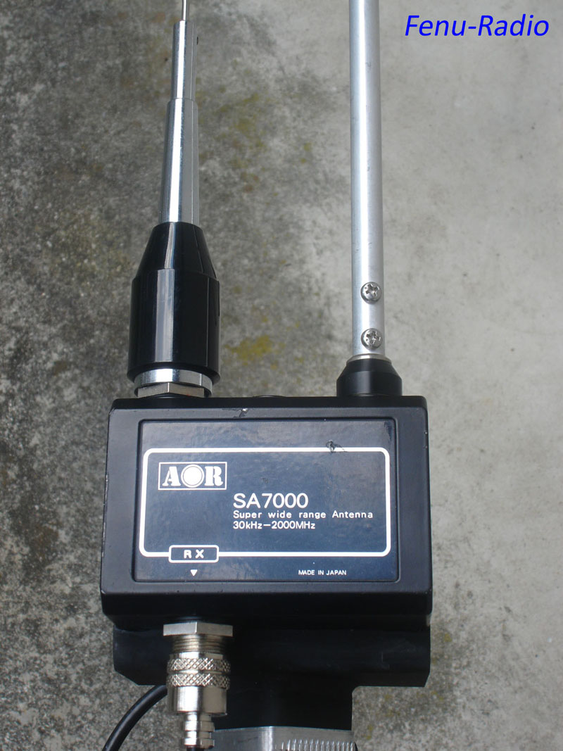
AOR SA-7000 Breitbandantenne
Die sehr bekannte und zudem auch sehr gute Aktivantenne ARA60 dürfte wohl eine der meist verbreitesten KW- Aktivantennen sein. Für Antennengeschädigte die einen guten KW- Empfänger besitzen, ist die ARA60 die ideale Antenne. Sie ist klein und lässt sich schnell am Balkongeländer montieren. Sofern keine Störer in der nähe sind, wie z.b. Fernseher usw., bringt sie sehr guten Empfang. Sie ist in der Verstärkung um ca. 10db regelbar. Aber Vorsicht: nicht alle Empfänger vertragen eine Aktivantenne. Der JRC NRD545 DSP mag die ARA60 überhaupt nicht. Er übersteuert !! Das ist sehr enttäuschend. Das liegt nicht an der ARA60, sondern am NRD545. Die alten NRD’s lieben die ARA60. Früher, als ich die Kombination NRD525/535 & ARA60 hatte, waren nie irgendwelche Grosssignalprobleme zu hören. Im Vergleich mit 20m Langdraht erzeugte die ARA60 mehr Rauschen. Sehr schwache Stationen kamen mit dem Langdraht besser, weil der Langdraht rein passiv ist, also keine elektronische Verstärkung wie bei der ARA60.
|


.jpg)
.jpg)


.jpg)
 CrossLoop/RLA4C
 CrossLoop/RLA4C

.jpg)
.jpg)
.jpg)


.jpg)
.jpg)


.jpg)
.jpg)


.jpg)
.jpg)


.jpg)
.jpg)


.jpg)
.jpg)


.jpg)

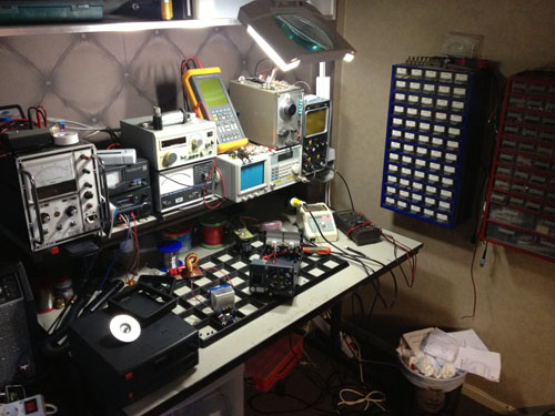 Hier wird
entwickelt und getüftelt.
Hier wird
entwickelt und getüftelt.
 Sitz von
Rafansys.
Sitz von
Rafansys.


.jpg)


.jpg)